29/07/26 Wed 14:04pm
Applications of FEA
they lie in the auto industry, the aero industry and the civil industry
benefits of using FEA and CAE
- enhanced design optimisation
- reduced development costs
- faster time to market
- improved safety and reliability
- material and resource efficiency
Steps involved in FEA:
pre processing
analysis
post processing
- Problem Definition:
- define objectives
identify goals such as stress analysis or thermal behaviour - geometry preparation
create or import the CAD model of the structure - material properties
assign relevant material properties ( elastic modulus, Poisonn’s ratio, etc)
- define objectives
Pre-processing
- Discretization
- Numbering of nodes and elements
- Selection of displacement function
Analysis - Define the material behaviour
- Derivation of element stiffness matrix and equations
- Assemble the element equations
- Applying boundary conditions
- Solution of unknown displacements
- Computation of the element stresses and strains
Post-processing - Interpret the results
Types of Elements
- 1d elements: line elements for trusses beams and frames ALSO RODS apparently
- 2d elements: triangular and quadrilateral shapes for planar or axisymetric problems
- 3d elements: tetrahedral, hexahedral and other polyhedral shapes for solid mechancal problems
- speical elements: Shell and plate elements for thin structures.
Nodes in FEA
Types of Nodes:
- Internal Nodes: found inside elements, crucial of calculations.
- Boundary nodes: located on edges or surfaces used to apply boundary conditions
- Master nodes: used to link nodes.
Pre-processing
- Discretization
- Numbering of nodes and elements
- Selection of displacement function
Analysis - Define the material behaviour
- Derivation of element stiffness matrix and equations
- Assemble the element equations
- Applying boundary conditions
- Solution of unknown displacements
- Computation of the element stresses and strains
Post-processing - Interpret the results
WARNING!
This portion of the notes is a little incomplete, if you see this and we’ve already gotten the class recordings leave a comment at the bottom of the page so i finish this bit
Step 2 meshing
mesh generation: divide the geometry into s aller finite elements
element selection chose element types (1d 2d 3d) based on the problem.
Step 3
step 5 post processing and interpretation :
visalization
key outputs
hotspot analysis
report generation
iterate:
validation:
Meshing in FEA
- meshing subdivides a geometry into smaller, simpler elements (finite elements)
- key step in Finite Element Analysis (FEA).
- converts complex domains into manageable discrete parts for computational analysis.
- Determines the accuracy, convergence, and computational cost of the solution.
Importance of Meshing in FEA
- Foundation of FEA Models: Defines how the geometry is divided into smaller, solvable elements.
- Accuracy of Results: Finer and well-structured meshes yield more precise results.
- Capturing Complex Geometries: Enables modelling of intricate shapes and details.
- Stress and Strain Gradients: Allows accurate representation of high gradient regions, such as near holes or notches.
- Computational Efficiency: Balanced meshing ensures acceptable accuracy without excessive computation time.
- Convergence Analysis: Gradual refinement of the mesh helps verify the stability and reliability of results.
- Adaptivity: Adaptive meshing techniques improve the mesh where errors are higher.
- Material and Element Behaviour: Affects how material properties and element formulations are implemented.
- Impact on cost and time: Well-designed meshes reduce the need for re-analysis, saving resources
Meshing types
- Meshing types decided based on shape & size of the problem model.
- Basic types of meshes are:
- Structured mesh
- Unstructured mesh
- Other mesh types are:
- Hybrid Mesh
- Adaptive Mesh
- Sweep Mesh
Structured Mesh
Regular grid, computationally efficient but less suited for complex geometries.
Unstructured Mesh
Flexible for irregular domains, ideal for complex geometries but computationally intensive
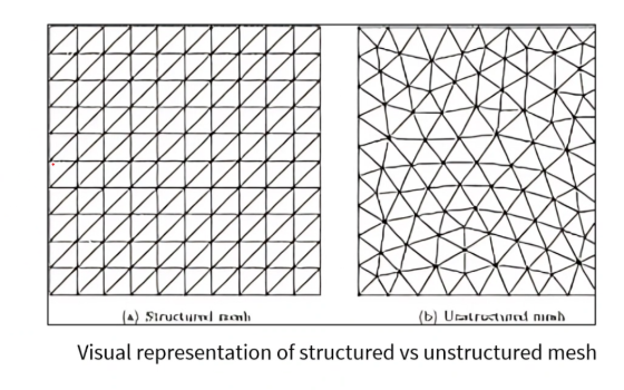
| Structured Mesh | Unstructured Mesh | |
|---|---|---|
| → Grid Layout | Regular, orderly grid of elements (e.g, squared, rectangles, cubes). | Elements have arbitrary shapes (triangles, tetrahedral, etc.). |
| → Element Connectivity | Each element shares common nodes with its neighbours. | Irregular shaped elements are present with uneven number of nodes. |
| → High Accuracy | Works well for simple, geometrically regular domains. | Suitable for complex or irregular shapes. |
| → Efficiency | Ideal for structured shapes like beams or simple mechanical parts. | Ideal for simulations of intricate shapes like automotive or aerospace parts. |
| → Flexibility | Struggles with complex, irregular geometries. | Easier to refine locally in regions of interest in complex geometries. |
Hybrid Meshing Techniques
- Combines Structured and unstructured meshing approaches.
- Structured meshes in simple regions, unstructured in complex areas.
- Reduces computational cost while maintaining accuracy.
- Commonly used in large-scale simulations with diverse geometric features.
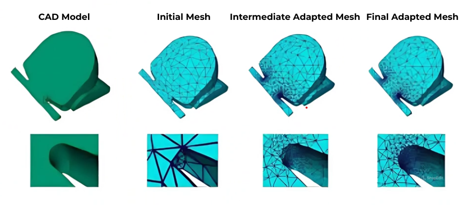
Adaptive Meshing Techniques
- Automatically refines mesh in high-gradient regions
- Iterative approach, adjusting the mesh based on solution errors.
- Balances accuracy and computational efficiency dynamically.
- Tools like COMSOL, ANSYS and ABAQUS support adaptive meshing.
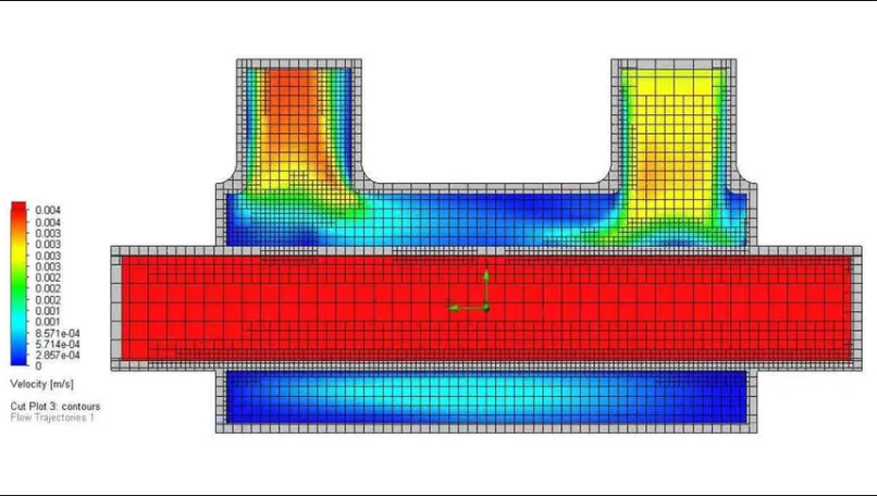
Meshing Tools & Techniques
- Process of dividing a geometry into smaller elements for FEA.
- Essential for accurate numerical simulation and computational efficiency.
- Automatic and manual options for meshing.
- Techniques vary based on geometry complexity and analysis types.
- Optimizing mesh quality and balancing accuracy with computational cost.
Quality Metrics for Meshing
- Aspect Ratio: Ideal elements have near-unity ratios.
- Skewness: Lower skewness ensures better numerical accuracy.
- Jacobian Ratio: Measures element distortion during meshing.
- Element Shape: Avoid highly irregular or elongated shapes.
- Mesh Independence: Verify results are unaffected by further mesh refinement.
============================================================
Application based questions
List the FEA workflow for the given EV components:
- Battery Pack Lifting Rod
- EV Motor Shaft
- Battery Mounting Bolt
- Suspension Tie Rod
- Battery Cooling Pipe Expansion
- Charging Cable Stretch
- Motor Mount Bolt
- Suspension Spring
Solutions:
1. Battery Pack Lifting Rod
The Scenario
“A battery pack weighs 520 kg. During assembly, it is lifted using four lifting rods. During testing, one lifting rod bends permanently. So, production stops.”
The Question is, Why did only one rod fail?
Is it because of
- Material?
- Diameter? (of the rod)
- Load sharing?
- Manufacturing defect?
FEA Problem → Represent each lifting rod as a 1D Bar Element and calculate
- Axial stress
- Elongation
- Factor of safety
2. EV Motor Shaft
The Scenario
“An Ev manufacturer increases motor torque from 250 to 400 Nm. After testing, the shaft twists excessively. The challenge is to redesign the shaft to meet 400 Nm.
Engineers must redesign the shaft.
Should we
- Increase diameter?
- Change material?
- Reduce torque?
1D Representation treats a shaft as a 1D Torsion Element
- Shear stress
- Angle of twist